
STM32 Board ARM Cortex-M4 Development STM32F407IGT6 STM32F407+ PL2303 USB UART Module Kit= Open407I-C Standard | Компьютеры и офис
Сохраните в закладки:


История цены
*История изменения цены! Указанная стоимость возможно, уже изменилось. Проверить текущую цену - >
| Месяц | Минимальная цена | Макс. стоимость | Цена |
|---|---|---|---|
| Mar-22-2026 | 0.11 руб. | 0.63 руб. | 0 руб. |
| Feb-22-2026 | 0.81 руб. | 0.86 руб. | 0 руб. |
| Jan-22-2026 | 0.85 руб. | 0.3 руб. | 0 руб. |
| Dec-22-2025 | 0.96 руб. | 0.50 руб. | 0 руб. |
| Nov-22-2025 | 0.23 руб. | 0.63 руб. | 0 руб. |
| Oct-22-2025 | 0.41 руб. | 0.78 руб. | 0 руб. |
| Sep-22-2025 | 0.54 руб. | 0.75 руб. | 0 руб. |
| Aug-22-2025 | 0.77 руб. | 0.44 руб. | 0 руб. |
| Jul-22-2025 | 0.43 руб. | 0.7 руб. | 0 руб. |
Новые товары
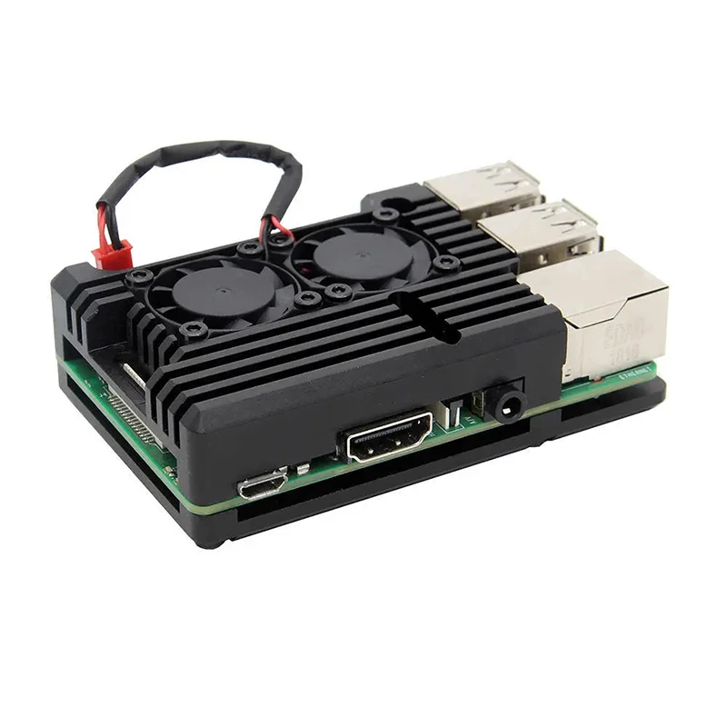
Raspberry Pi 3 Model B Plus специальный алюминиевый чехол с двойным охлаждающим
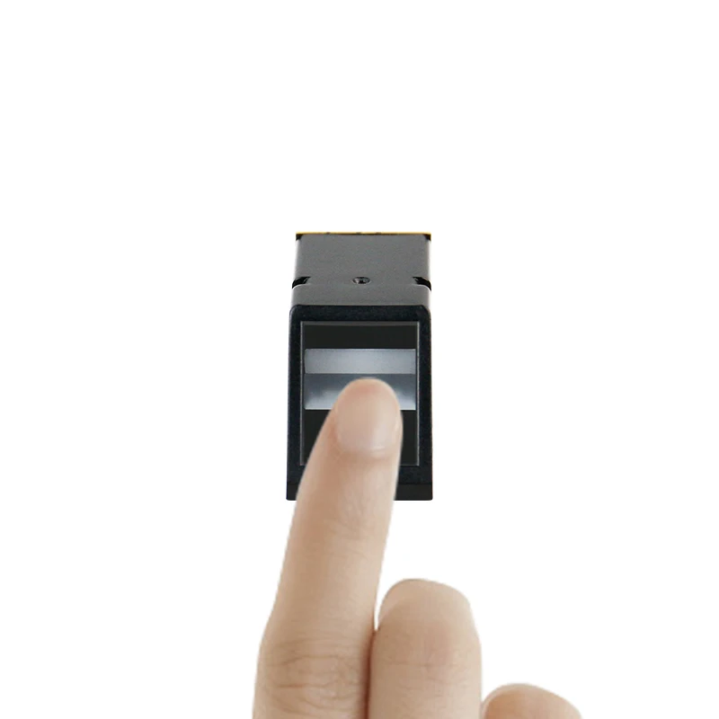
Модуль Yahboom AS608 объединяет оптический путь и функции обработки отпечатков пальцев для Raspberry Pi Micro:bit Jetson Nano.
1469.65

Металлический корпус (А) с вентилятором для платы расширения Raspberry Pi Compute Module 4.
909.38

Оригинальный ST-Link V2 Stlink St Link STM32 STM8 MCU USB JTAG In-circuit Debugger/Programmer/Emulator.

Ядро STM32F405 для разработки платы IoT PyBoard на.
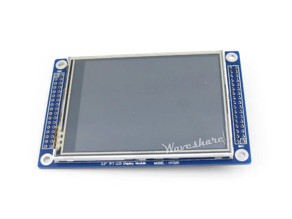
HY32D 3.2 дюйма 320 * 240 ЖК-сенсорный экран Дисплей XPT2046 Контроллер сенсорного экрана ILI9325 TFT модуль.
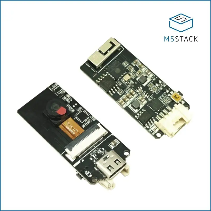
Официальная макетная плата модуля камеры M5Stack ESP32 (OV2640) | Демонстрационные стенды
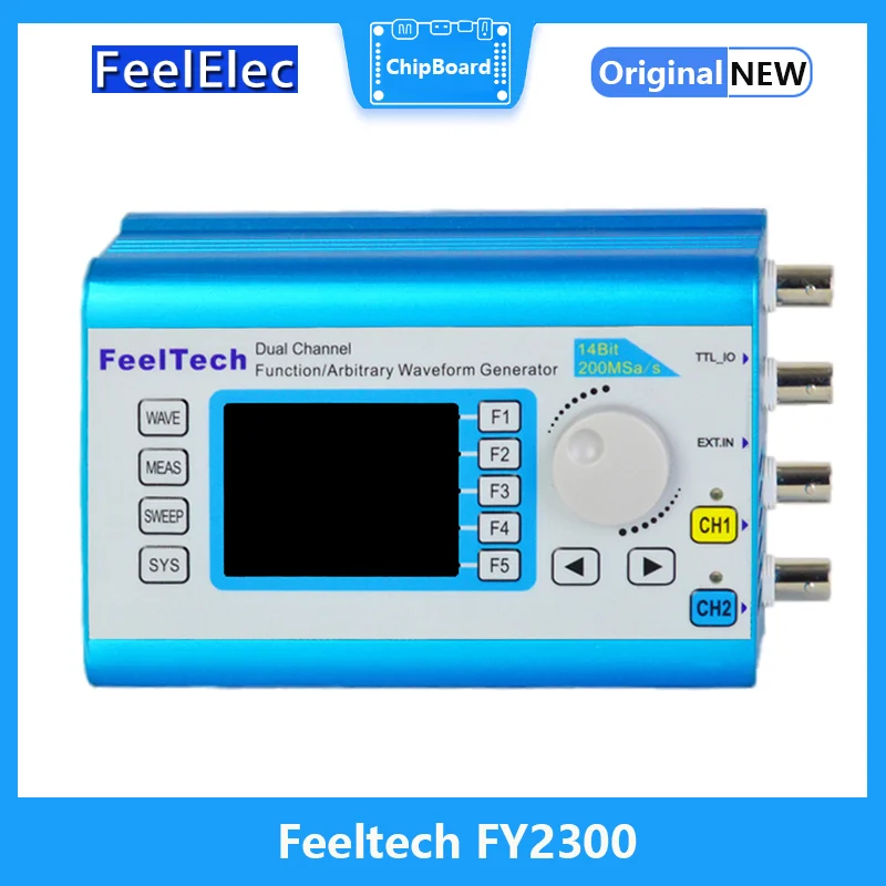
Русский: Многофункциональный сигнальный генератор высокой стабильности с двумя каналами Feeltech FY2300 12M 20M Digital DDS Function Frequency Meter.
7182.69
Характеристики
STM32 Board ARM Cortex-M4 Development STM32F407IGT6 STM32F407+ PL2303 USB UART Module Kit= Open407I-C Standard | Компьютеры и офис
Описание товара
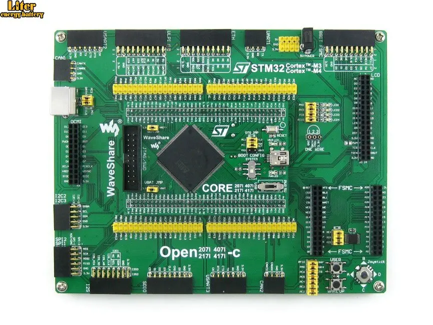
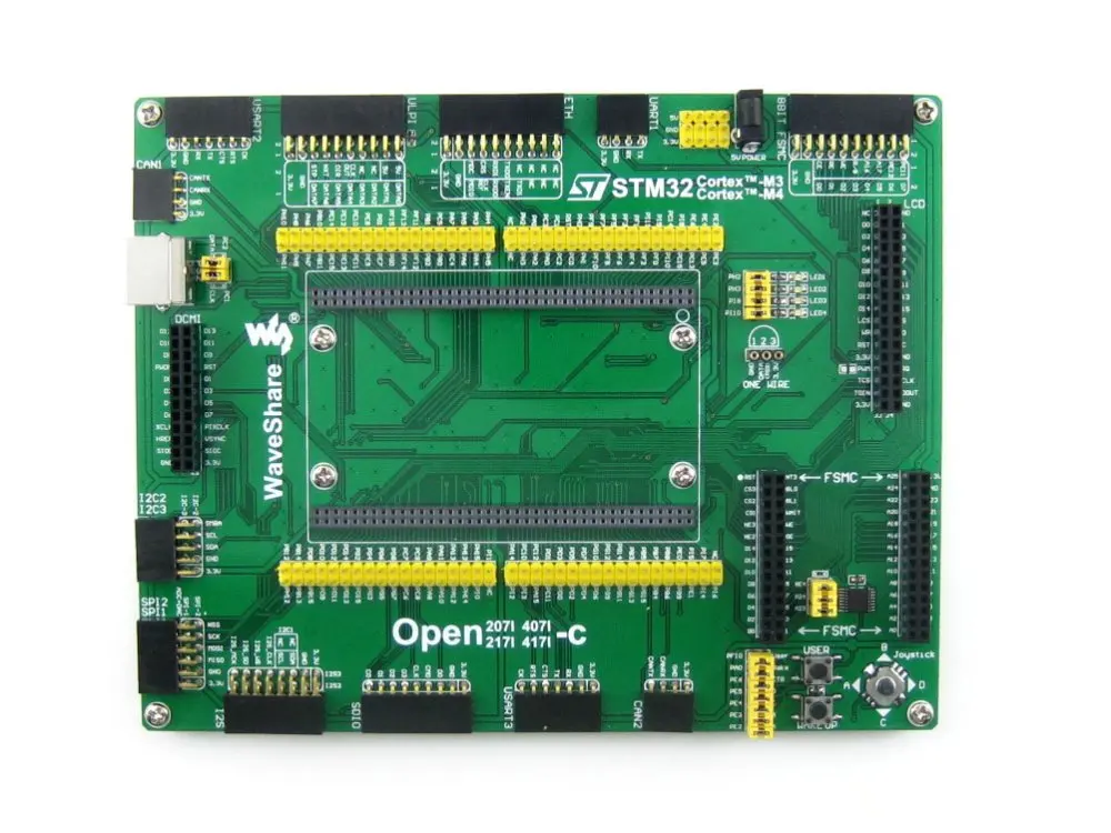
STM32 development board designed for the STM32F407IGT6 MCU, and integrates various standard interfaces, pretty easy for peripheral expansions.
What's on the mother board
Photos![STM32 Development Board]()
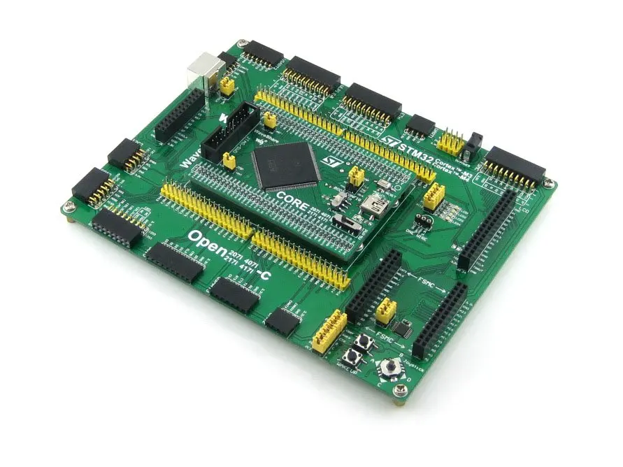
Open407I-C development board![STM32 Development Board]()
Open407I-C development board![STM32 Development Board]()
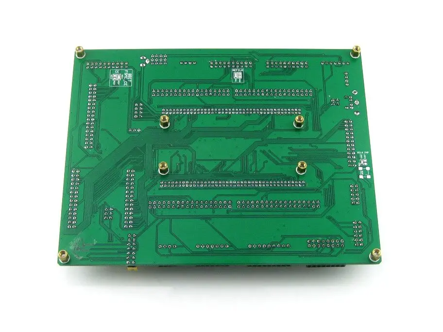
Open407I-C development board back view![STM32 Development Board]()
Open407I-C mother board![STM32 MCU Core Board]()
MCU core board Core407I![STM32 MCU Core Board]()
MCU core board Core407I![STM32 Development Board]()
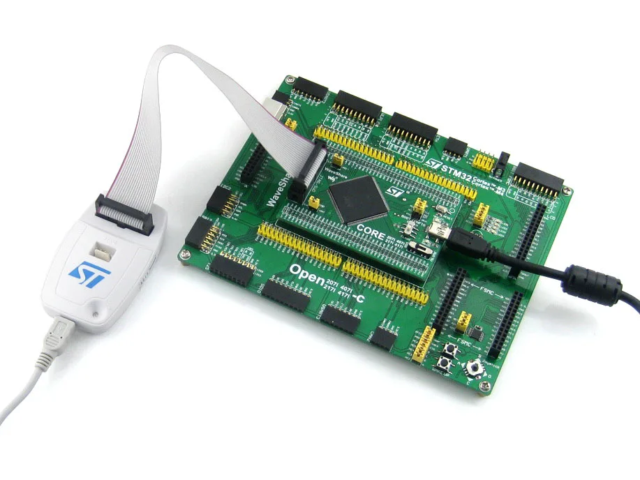
Connecting to a debugger
Connecting to various peripherals![]()
Open407I-C μC/OS-II (1)![]()
Open407I-C μC/OS-II (2)![]()
Open407I-C μC/OS-II (3)![]()
Open407I-C μC/OS-II (4)![USB Device]()
Connecting to USB device through OTG cable![USB3300 USB HS Board]()
Connecting to USB3300 USB HS Board![UDA1380 Board]()
Connecting to UDA1380 Board![OV9655 Camera Board]()
Connecting to OV9655 Camera Board![RS232 Board]()
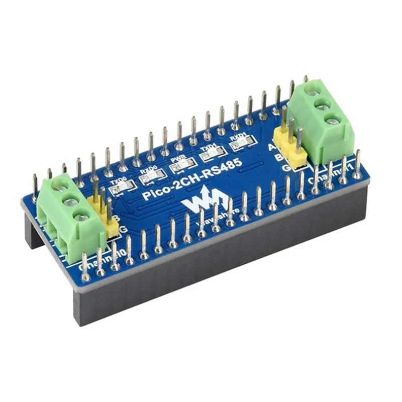
Connecting to RS232 Board![RS485 Board]()
Connecting to RS485 Board
Connecting to USB UART Board![SN65HVD230 CAN Board]()
Connecting to CAN Board![8 Push Buttons]()
Connecting to 8 Push Buttons![5 IO Keypad]()
Connecting to 5 IO Keypad![AD Keypad]()
Connecting to AD Keypad![Analog Test Board]()
Test Board on the AD/DA port![FM24CLXX FRAM Board]()
Connecting to FRAM Board![I2C cascading x3]()
Multi I2C peripheral Module connected to the I2C bus![AT45DBXX DataFlash Board]()
Connecting to DataFlash Board![VS1003B MP3 Board]()
Connecting to VS1003B MP3 Board![NRF24L01 RF Board]()
Connecting to NRF24L01 RF Board![Micro SD Storage Board]()
Connecting to Micro SD Storage Board![NandFlash Board]()
Connecting to NandFlash Board![NorFlash Board]()
Connecting to NorFlash Board![SRAM Board]()
Connecting to SRAM Board![DP83848 Ethernet Board]()
Connecting to Ethernet Board![Connecting to any accessory board]()
Connecting to any accessory board you need
JTAG/SWD interfaces
![JTAG Header Pinout]() Figure 2. SWD Header Pinout
Figure 2. SWD Header Pinout
![SWD Header Pinout]()
Development Resources
Package Contains Open407I-C development board x 1 PL2303 USB UART Board (mini) x 1 USB type A plug to mini-B plug cable x 1 USB type A receptacle to mini-B plug cable x 1 4-pin wire x 2 2-pin wire x 2 USB power cable x 1 User Guide CD x 1 1![]() 2
2 ![]() 3
3 ![]() 4
4 ![]() 5
5 ![]() 6
6 ![]() 7
7 ![]() 8
8 ![]()

Open407I-C is an STM32 development board designed for the STM32F407IGT6 microcontroller, consists of the mother board and the MCU core boardCore407I.
The Open407I-C supports further expansion with various optional accessory boards for specific application. The modular and open design makes it the ideal for starting application development with STM32F4 series microcontrollers.
What's on the mother board

For jumpers 27-30:
short the jumper to connect to I/Os used in example code open the jumper to connect to other custom pins via jumper wires What's on the Core407I
Photos

Open407I-C development board

Open407I-C development board

Open407I-C development board back view

Open407I-C mother board

MCU core board Core407I

MCU core board Core407I

Connecting to a debugger
Connecting to various peripherals

Open407I-C μC/OS-II (1)

Open407I-C μC/OS-II (2)

Open407I-C μC/OS-II (3)

Open407I-C μC/OS-II (4)

Connecting to USB device through OTG cable

Connecting to USB3300 USB HS Board

Connecting to UDA1380 Board

Connecting to OV9655 Camera Board

Connecting to RS232 Board

Connecting to RS485 Board
Connecting to USB UART Board

Connecting to CAN Board

Connecting to 8 Push Buttons

Connecting to 5 IO Keypad

Connecting to AD Keypad

Test Board on the AD/DA port

Connecting to FRAM Board

Multi I2C peripheral Module connected to the I2C bus

Connecting to DataFlash Board

Connecting to VS1003B MP3 Board

Connecting to NRF24L01 RF Board

Connecting to Micro SD Storage Board

Connecting to NandFlash Board

Connecting to NorFlash Board

Connecting to SRAM Board

Connecting to Ethernet Board

Connecting to any accessory board you need
Note:
The Open407I-C supports programming via STM32 UART bootloader, a USB TO UART accessory board is also provided in the package.
The Open407I-C does NOT integrate any debugging function, a debugger is required.
JTAG/SWD interfaces
The figure 1, and 2 show the header pinouts of JTAG/SWD interface
Figure 1. JTAG Header Pinout Figure 2. SWD Header Pinout
Development Resources
The User Guide CD includes development resources listed as follow:
Related software (KEIL etc.) Demo code (examples in C, μC/OS-II) Schematic (PDF) STM32 development documentations (Datasheet etc.)Package Contains Open407I-C development board x 1 PL2303 USB UART Board (mini) x 1 USB type A plug to mini-B plug cable x 1 USB type A receptacle to mini-B plug cable x 1 4-pin wire x 2 2-pin wire x 2 USB power cable x 1 User Guide CD x 1 1
 2
2  3
3  4
4  5
5  6
6  7
7  8
8 
Трекер стоимости
Отзывы покупателей
Новые отзывы о товарах

Татьяна Румняцева 18 Декабря 2021, 13:50 #
Пальто очень понравилось. Для меня только одни плюсы: довольно теплое, стильное, давно искала именно такую верхнюю одежду. Ношу уже не... Читать отзыв полностью...

Анастасия 20 Декабря 2021, 10:39 #
Заказывала платье S размера. Подошло отлично, так как перед заказом лучше всего измерять свои параметры. Доставка была быстрой, без... Читать отзыв полностью...

Михаил 19 Декабря 2021, 16:24 #
Покупал для себя такой удлинитель USB. Пользуюсь ним каждый день. Очень удобно, не надо лазать под столом, чтобы вставить флешку... Читать отзыв полностью...

Юлия 18 Декабря 2021, 23:46 #
Заказывала футболку чёрного цвета с современным дизайном. Приятно прилегает к телу, сильно не мнется. Цвет после стирки остался прежним, что... Читать отзыв полностью...
Юлия 18 Декабря 2021, 23:02 #
Приобрела для себя такую сумку, так как очень люблю габаритные сумки. Длинная ручка через плечо очень удобная. Сама по себе... Читать отзыв полностью...

Анна 18 Декабря 2021, 21:41 #
Супер классный, удивительно красивый, а главное качественный и удобный сдельный купальник. Высокая линия бедер этого слитного купальника черного цвета зрительно... Читать отзыв полностью...

Покупала кошелек на подарок. Очень понравился. Достаточно отделений для карточек, можно вставлять даже 2 карточки в одно. Кнопка-застежка функционирует хорошо.... Читать отзыв полностью...